Calibrating an RGB keyboard
Ok, this might seem simply too much. And it is. But it’s been fun and colorful… so, why not trying it yourself?!
A little backstory: I was looking for a new keyboard. I’ve been using mechanical keyboards for more than 8 years and during this time I could experience many different types of switches, keycaps, layouts. But the more I learned and experienced, the more unsure I felt about what switches my next keyboard would have.
One day I end up on the GMMK website and got pretty interested in their tenkeyless keyboard: an hotswappable, RGB backlit, alluminum keyboard for less than 80€? Ok, you still have to factor in the switches and the keycaps which easily can make up for 2/3 of the price of a keyboard. But if you, like me, already have those laying around somewhere in your house…
The switches
So I ordered the keyboard and it arrived in just a couple of days. Beautiful and sturdy, I decided to install the only switches I had already unsoldered and cleaned up: MX Blacks. As for the keycaps, I used the ones I had on my previous keyboard, a TKL Varmilo VA88M. Oh boi, the sound of solid, high quality PBT keycaps on a linear switch mounted on a dampened, alluminum keyboard… so neat!
But because of those switches I was losing completely the RGB backlight: not a single ray of RGB eye-catchery was peeking through the pitch blackness of them MXes! Not only that: as smooth and silky the typing experience was, I always preferred slightly lighter, tactile switches, such as MX Browns.

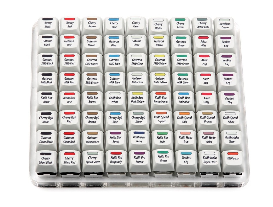
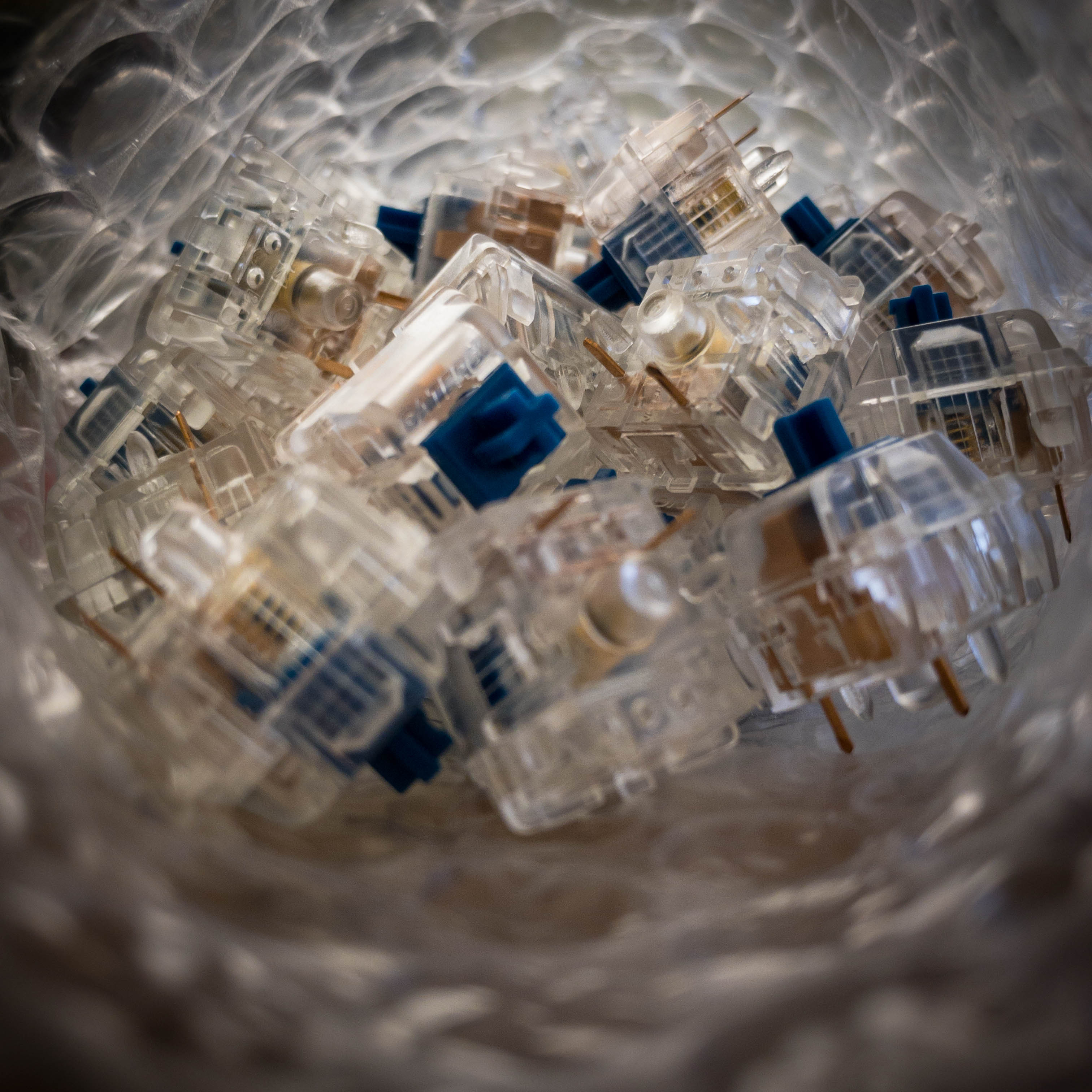
A friend of mine had a switch tester laying around the office, so I borrowed his and played with it: the first thing that I understood was that, regardless of the switch I ended up choosing, it had to be silenced. In the end I went for the Zilent v2 76g tactile switches: they’re very tactile, they’re silent, transparent… and VERY expensive. I ordered them directly from the maker’s website and after just three days they arrived from Canada!

The RGB issue
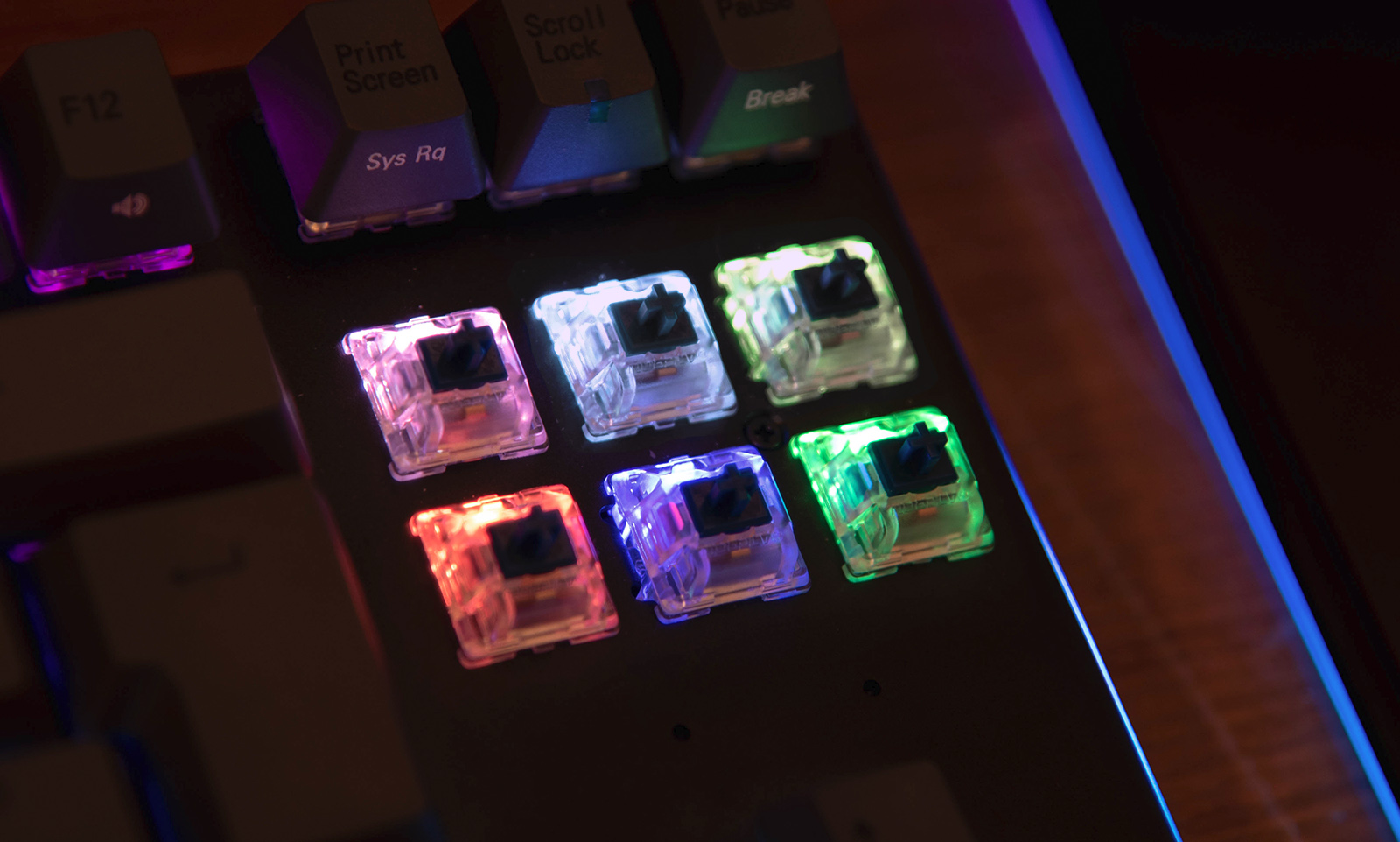
I don’t want (yet?!) to turn this into a mechanical keyboard blog so I’ll spare you the details of how smooth and bumpy and lovely these switches are. No. Instead, I want to share with you a little annoyance I got once I fully assembled the keyboard and could finally play with the RGB lightning. Basically, the colors are way off. Ok, I know, it’s not a display so who cares. But when I say they’re off, I do really mean it. Like, blue that’s more like teal, purple that’s pink, orange that’s just a warm white..

In the image above you can see what I mean. Let’s say you want to display the color ██#FF8040. Normally you’d convert from HEX to RGB, obtaining {255, 128, 64}, then type these values in the keyboard’s management software and… you’d get the first (top-left) color in the above picture! But that’s pink-ish white, not salmon-orange!
The calibration
This is a well known issue you’d normally find in computer monitors, TVs, cameras, printers. Any device that either shows or captures colors is affected by it and the discrepancy between expected and actual colors is usually solved through calibration.
Calibration is the process of adjusting the color response of a device to some reference value. In my case, the calibration source will be the keyboard’s RGB LEDs and the calibration target will be my color-calibrated monitor. Yes, this will be a totally biased and subjective calibration, performed using my own eyes and personal judgment.
Step 1 - Generating input data
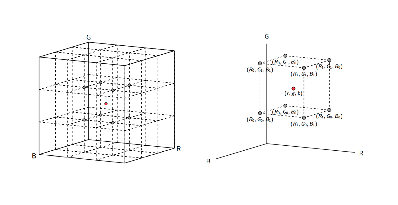
We first need to generate a 3D color matrix, where each dimension represents a color component (R, G, B). How many samples each dimension will have it’s up to you, but I strongly advise sticking to very small numbers, such as 4 or 5. In my case, I went with 5 samples per channel for a total of 53 = 125 unique colors.
Of course, having more colors in this matrix will definitely increase the accuracy of the calibration. But we’re using our own eyes instead of a colorimeter: it will be impossible for you to tell the difference between ██#FF8040 and ██#FF8030; not to mention the time it will take to manually type each color in the keyboard’s software 😉.
For this project I’m going to use Powershell. So, to start, we’d need something like this:
$lut[  0,  0,  0]=@(0,0,0)
$lut[  0,  0, 63]=@(0,0,0)
$lut[  0,  0,127]=@(0,0,0)
$lut[  0,  0,191]=@(0,0,0)
$lut[  0,  0,255]=@(0,0,0)
$lut[  0, 63,  0]=@(0,0,0)
$lut[  0, 63, 63]=@(0,0,0)
...
Step 2 - Generating calibrated values
This is the colorful part. The steps are very repetitive and boring:
- open paint
- make a custom color that matches the n-th input sample in the above matrix
- paint a big blob of color in the document
- open the keyboard software
- pick the same color and set it to some key
- the goal is to have it match the color on the screen: if it doesn’t, try fiddling a bit with the RGB channels until it does
A couple of tips that might save you some time:
- calibrate the white color before everything else: in my case, 255 to all channels produced a green-ish tint! Keep in mind this information for later, it will give you an important suggestion about what channel is the predominant one in your RGB LEDs
- calibrate one channel at a time
- for each channel start with the brightest color (255), then with the one above zero (63) and finally the rest
- it’s the best to perform the procedure in a dark room, with all the lights turned off
- turn off all the other LEDs on the keyboard as well
If you have some translucent, white plastic (such as teflon), put it above the RGB light you’re using for calibration. The idea is that since the RGB LED is made up of three very small LEDs, one for each channel, you need a translucent material between it and you. The output of each LED will then go inside the material, get scattered inside it, blend with the other colors and then finally exit, resulting in a much smoother, better representation of the actual color.
It’s also worth mentioning that you’ll probably find particularly challenging calibrating low brightness values. This is perfectly normal and stems from the fact that light intensity scales logarithmically, not linearly.
Finally, keep in mind that you’re comparing a pure color originating from a colored LED to the one produced by your monitor, which most probably is generated by a white LED backlight passing through an LCD matrix. Don’t worry, then, if you end up matching some color with much smaller intensities in the LEDs, or if a “pure green” in the target requires some small quantities of either red or blue.
Step 3 - Let’s write some code!
Once you’ve mapped all target colors to the best possible values to your LEDs, it’s time to write the script that will convert any target color to the calibrated value on your keyboard.
First, we need to convert input colors from HEX to RGB:
$inputColor = $inputColor.Replace('#','')
$r = [int64][System.Convert]::ToInt64($inputColor.Substring(0, 2), 16)
$g = [int64][System.Convert]::ToInt64($inputColor.Substring(2, 2), 16)
$b = [int64][System.Convert]::ToInt64($inputColor.Substring(4, 2), 16)
Then we need to obtain the sub-matrix in which the input color falls into:
function Get-InterpBounds([Parameter(Mandatory)][Int64]$x)
{
    $div = [double]$x / 64.0
    $intPart = [math]::floor($div)

    [double]$lowerBound = [math]::Max(0, ($intPart * 64)-1)
    [double]$upperBound = ($lowerBound -gt 0) ? ($lowerBound + 64) : ($lowerBound + 63)
    [double]$offset = [double]($x-$lowerBound)/[double]($upperBound-$lowerBound)

    return @($lowerBound, $upperBound, $offset)
}

The above takes into consideration the fact that each dimension in my source matrix has been sampled at (0, 63, 127, 191, 255). Once we are able to determine the bounds for each channel, we perform trilinear interpolation to get the color-corrected value:
function Get-Interp3D($r, $g, $b, $lut)
{
    $pR = Get-InterpBounds $r
    $pG = Get-InterpBounds $g
    $pB = Get-InterpBounds $b

    $c000 = $lut[[int]$pR[0]][[int]$pG[0]][[int]$pB[0]]
    $c001 = $lut[[int]$pR[0]][[int]$pG[0]][[int]$pB[1]]
    $c010 = $lut[[int]$pR[0]][[int]$pG[1]][[int]$pB[0]]
    $c011 = $lut[[int]$pR[0]][[int]$pG[1]][[int]$pB[1]]
    $c100 = $lut[[int]$pR[1]][[int]$pG[0]][[int]$pB[0]]
    $c101 = $lut[[int]$pR[1]][[int]$pG[0]][[int]$pB[1]]
    $c110 = $lut[[int]$pR[1]][[int]$pG[1]][[int]$pB[0]]
    $c111 = $lut[[int]$pR[1]][[int]$pG[1]][[int]$pB[1]]

    $c00 = Get-Lerp3D $c000 $c100 $pR[2]
    $c01 = Get-Lerp3D $c001 $c101 $pR[2]
    $c10 = Get-Lerp3D $c010 $c110 $pR[2]
    $c11 = Get-Lerp3D $c011 $c111 $pR[2]

    $c0 = Get-Lerp3D $c00 $c10 $pG[2]
    $c1 = Get-Lerp3D $c01 $c11 $pG[2]

    $c = Get-Lerp3D $c0 $c1 $pB[2]

    return [math]::Round($c[0]), [math]::Round($c[1]), [math]::Round($c[2])
}
The Get-Lerp3D function is just a simple linear interpolation.
Wrapping it up
Once everything’s been done, we can simply invoke the script in the shell like this:
 It’s cool! At this point you should have an understanding of how color correction works. Of course, applying it to a keyboard it’s blatantly overkill and useless. But who knows, maybe you can try and calibrate your christmas lights for the next year! 🤣
Cheers!